Forward Kinematics
title: "Forward Kinematics"
keywords:

- Open-Chain
   - Forward
   - Kinematics
   - End-Effector
   - Robotics
Terms:
Forward Kinematics
- Refers to the use of the kineamtic equations of a robot to compute the position of the end-effector from specified values for the joint parameters.
End Effector
Device at the end of a robotic arm designed to interact with the environment.
- End effectors are typically the grippers of a robot
Denavit-Hartenberg Parameters
Referred to as D-H Parameters
Commonly used convention for selecting frames of reference to the links of a spatial kinematic chain
Product of Exponentials
Referred to as PoE
Adjacent frames do not need to be considered.
Only 2 frames are needed: Space Frame {s} and Tool Frame {b}
6n numbers are needed to describe n screw axes
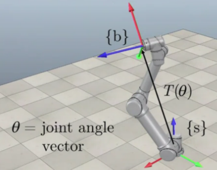
Forward Kinematics
- Forward kinematics refers to the use of the kinematic equations of a robot to compute the position of the end-effector from specified values for the joint parameters.
Problem
Define a frame {s} (often fixed at the base of a robot) and a frame {b} at the end effector of the robot arm.
Calculate the Forward Kinematics of the robot: I.e.,
Representing Forward Kinematics in the {s} Frame
Procedure:
Let M be the transformation matrix of the end-effector frame {b} when = 0
In other words, M is the position and orientation of the end effector when all joint angles are set to zero:
The first three 3-vectors (x,y,z) denote which axis in the {s} frame corresponds to a value in the {b} frame. For example, a value of in the first column means that the x axis of the {b} frame is aligned with the positive y axis of the {s} frame
The bottom row is added to simplify matrix operations
The represents the sum of all of the links from the space frame {s} to the end effector.
Find the {s} frame Screw Axes for each of the n joint axes when
The first 3-vector (angular velocity) represents which axis the space frame {s} is rotating about. For example, a value of means that this joint in the {s} frame is rotating about the positive z-axis
The linear velocity v can be found by identifying which axis is tangental to the turntable created at the center of the joint n and then multiplying that number with the distance that the joint is from the origin of the {s} frame.
Given , calculate the product of exponentials (PoE) formula in the space frame:
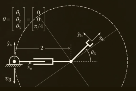
Example:
Given a 4 joint RRRP Robot Arm, find the Forward Kinematics:
1st, Find M:
2nd, Find all Screw Axes:
Note, for , the angular velocity is 0 because joint 4 is a prismatic joint which can only slide
3rd, that's it!
We now have the elements necessary to calculate the forward kinematic of the robot T() for any given theta
Representing Forward Kinematics in the {b} Frame
Procedure:
Unchanged: Let M be the transformation matrix of the end-effector frame {b} when = 0
Find the {b} frame Screw Axes _{1}, ..., _n for each of the n joint axes when = 0
The first 3-vector (angular velocity) represents which axis the space frame {b} is rotating about. For example, a value of [0,0,1]^T means that this joint in the {b} frame is rotating about the positive z-axis
The linear velocity v can be found by identifying which axis is tangental to the turntable created at the center of the joint n and then multiplying that number with the distance that the joint is from the origin of the {b} frame.
Given , calculate the product of exponentials (PoE) formula in the space frame:
Example:
Given a URRPR spatial open chain robot, determin the screw axis in {b} when the robot is in its zero position. L = 1.
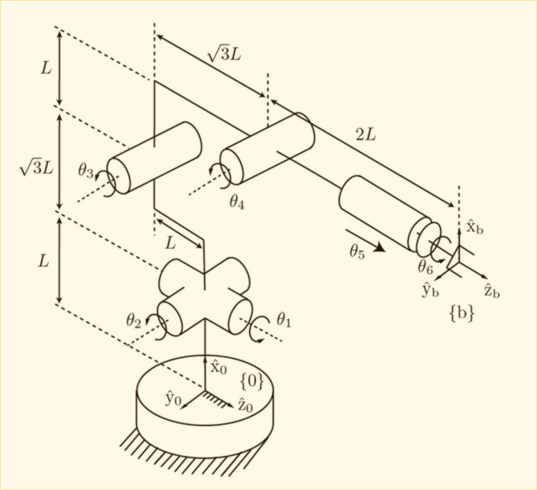
1st, Find M:
2nd, Find all Screw Axes:
Calculating the linear velocity looks complicated but is still quite simple. Take a look at . If you were to map that rotation onto the body frame {b}, you would notice that axis y is tangential to the rotation. It is also 2.73 units away from the {b} frame which is why it gets the value assigned.
Next, take a look at . It's rotation is tangential to both the x and z frames, so those will be assigned values. It is translated along the axis by a unit of 2.73 and along the axis by a unit of 2.73. The sign is produced from applying the multiplication formula: . Here, - is (0,-1,0), which will invert the sign of the z axis.
Alternatively, you could just apply the formula for each vector to determine the linear velocity. Less error prone even though it takes more time.
3rd, that's it!
We now have the elements necessary to calculate the forward kinematic of the robot for any given theta